DIY Exup Servo Sub
-
- Regular Poster
- Posts: 82
- Joined: Wed May 14, 2003 3:34 pm
DIY Exup Servo Sub
DIY Exup Servo Sub
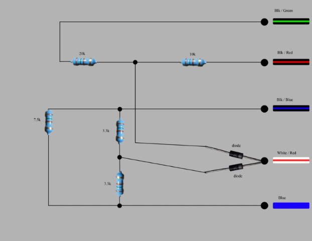
I’ll take no credit it as this is not my design so thanks to Steveakus & the guys in the Yamaha single “thumper talk ” forum just Google it
It took a while to find but designer has posted details of the circuit theory design development and testing.
The circuit seems to work on a whole range of bikes from the 250s to R1’s and of course the FZR Exup
No more Tacho tango , rev-counter fault codes etc as it matches the correct signals ( return voltages )
So I have built one and tested it on my YZF 750 & my T’Ace engine version and it works a treat
I used the plug connector off an old servo and just plugged it in "easy mod"
Only thing I would suggest you look at is using larger wattage resistors , as the ¼ W are a bit fragile to be used by themselves
Just solder them together and wrap in amalgamating tape or ” pot” with epoxy 2 part glue or if you feel posh use a circuit board
The loom / wiring colours vary by bike but its easy to figure out
Crommie
-
- Help!!! I need a LIFE!!!
- Posts: 3519
- Joined: Thu Jan 26, 2006 6:35 pm
- Location: Edmonton, Alberta
Which way are the diodes supposed to be placed if you wouldn't mind sir?
Thanks very much though, very cool, and very handy
Michael
Yes Yes I know, I said, I'm building a project YZF1070
Basement is done now, 850 finished and gone...
Gotta get the new siding up on the house.
Fixing the FZ1 up, cleaning up garage and then I might even begin
Yes Yes I know, I said, I'm building a project YZF1070
Basement is done now, 850 finished and gone...
Gotta get the new siding up on the house.
Fixing the FZ1 up, cleaning up garage and then I might even begin
-
- Regular Poster
- Posts: 82
- Joined: Wed May 14, 2003 3:34 pm
Cam thats correct the diodes pass voltage towards the Wht / Red ( so the diode's silver band end is connected to the Wht / Red
some more info cut & pate form his posts
just google Steveakus Servo sub
Steveakus0 9-02-2008, 07:06 AM
Link To Diagram (http://www.mfpbuilt.com/resources/SimpleDiagram.pdf)
Ok I have had lots of requests for this to be better explained and also to have a better diagram, so : :prof:
The Engine Control Module reads a POT in the servo motor that references its position to the exup valve that creates more or less backpressure in turn createing a leaner or richer situation in the chamber.
So the voltage reference of the servo assembly ranges from .5 to 4.5 volts, there are the two wires that control the motor position (blk/red and blk/grn 12v multiplied by time to reach position required)
Then there are the three wires for the POT
Blue = 5v in
Wht/red = Reference to ECM (.5 to 4.5v)
blk/blue = common/grnd/return ohm reference (7) can slightly vary (7.5)
When you first turn your key on the servo motor sweeps (meaning it goes from-to each stop) You have to be able to replicate the movement of the servo, in real time
so my design has a Half valve closed reading (2.5v) at lowest, letting the bike stay a little richer than stock(at least acording to the valve position), and when it recieves a signal to close or open it gives it a 4v reading to tell the computer that infact it is adjusting and not in a "stuck position" (singal voltage reading out to ref. wht/red)
Here is what the finished product should look like :
http://i294.photobucket.com/albums/mm88 ... iagram.jpg
http://i294.photobucket.com/albums/mm88 ... Sub080.jpg
-
- Veteran Poster
- Posts: 147
- Joined: Wed Jun 18, 2008 7:30 am
- Location: South Africa
-
- Veteran Poster
- Posts: 147
- Joined: Wed Jun 18, 2008 7:30 am
- Location: South Africa
One of the gears of my servo got stripped, partially because of age and partially because of some deteriorating cables, so I built myself one, it really is not such a major job. Unfortunately i got foncused with the wiring to the servo and stoppped right there with the instalation. I rather machined a gear at work and installed it.
The wiring on the Fizzer is a different colour as the diagram, so I didn't want to take any chances with it, might pop the CDI? I'd still like to try it out, but first want to make sure of the wiring. Anyone else tried it as yet?
-
- Help!!! I need a LIFE!!!
- Posts: 520
- Joined: Sun May 27, 2007 2:27 am
- Location: Aberdeenshire, UK
Re: DIY Exup Servo Sub
Anyone actually built this one? I've just been on the Maplin website and have been blown away by the choice of resistors and diodes...
Dave
Dave
1993 YZF 750 SP with Yoshimura half system
RG400
GSXR 1100WT
RG400
GSXR 1100WT
-
- Dolphin-headed purple plasma TLR thing?
- Posts: 3839
- Joined: Mon Jan 29, 2007 7:12 pm
- Location: Melbourne. Australia
Re: DIY Exup Servo Sub
Dave, I think the reply with that drawing in the other post was a quote from MIkeSS here on the forum, he said he had made one and it was all good. PM him. Cheers.
-
- Help!!! I need a LIFE!!!
- Posts: 520
- Joined: Sun May 27, 2007 2:27 am
- Location: Aberdeenshire, UK
Re: DIY Exup Servo Sub
Cheers I'll drop him a line
Dave
Dave
1993 YZF 750 SP with Yoshimura half system
RG400
GSXR 1100WT
RG400
GSXR 1100WT
-
- Dolphin-headed purple plasma TLR thing?
- Posts: 3839
- Joined: Mon Jan 29, 2007 7:12 pm
- Location: Melbourne. Australia
Re: DIY Exup Servo Sub
Hey Scheffers....