Looking good, Tim. I thought my bike was in a lot of pieces...you win!
Trans Swap


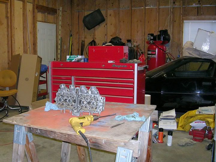
This might make Tim nervous, but here it is....
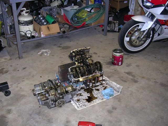
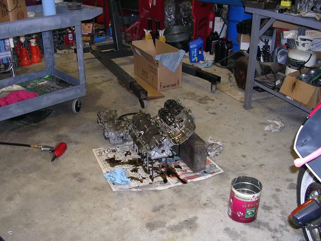
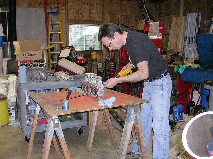
Torn down or tore up - I'm not sure which really.
There is a lot of cleaning to do from where it is right now.
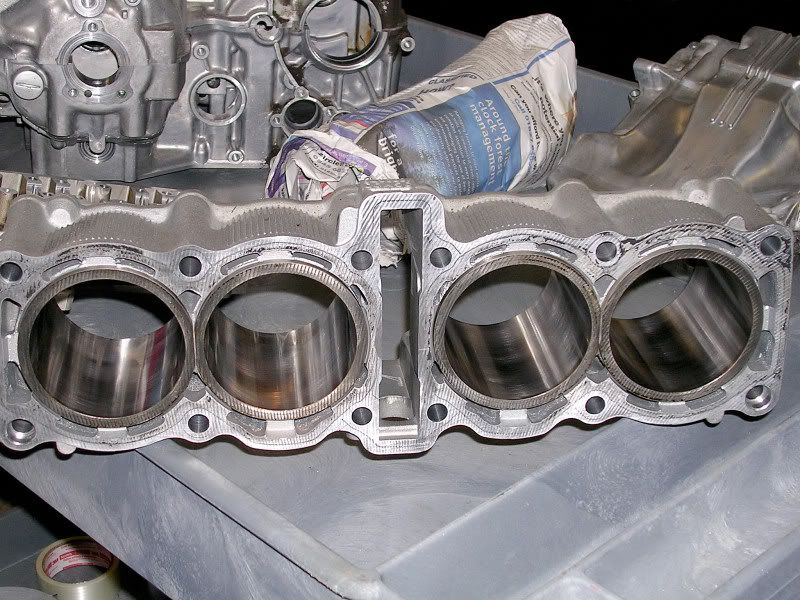
We did check the cylinders with a dial bore guage, and they look to be in good shape. They will be getting a trip to the machine shop for a glaze-break hone job.
I will also be replacing the output shaft bearing before the new gears go in, and replacing the valve stem seals as long It's down this far.
I'll try to get some better pics of the bits when they're cleaned up and ready to go back together.
That's all for now folks..................
Does anyone look up here anyway?
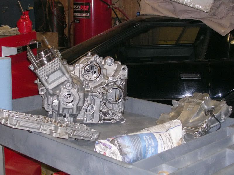
The pile of clean parts is growing larger, here's a few pics of the progress so far.
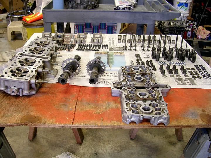
Cylinders were honed up nicely, and lot's of general cleaning work has been done. Big thanks to my pal Brad at X-act machine for letting me use a bit of his shop to get this done.
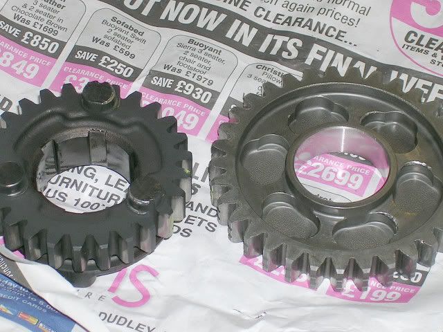
The gears provided a bit of a surprise - There was quite a bit of rounding on the second gear engagement dogs, and I'm waiting for a replacement set to find it's way here from Japan as I write this. I could not in good conscience build an engine with parts that I suspect wouldn't last too long, so (sigh) it's a bit of a hold up.
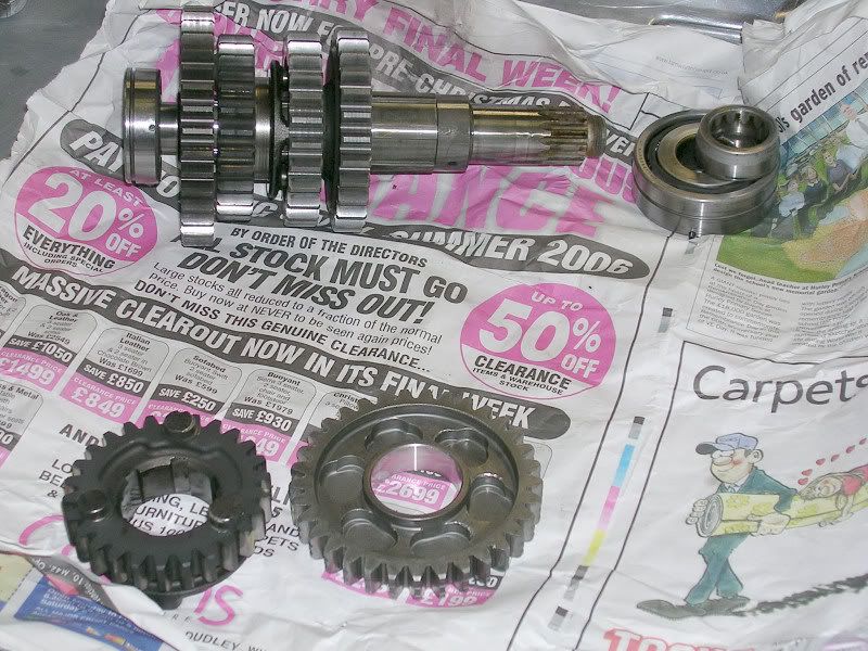
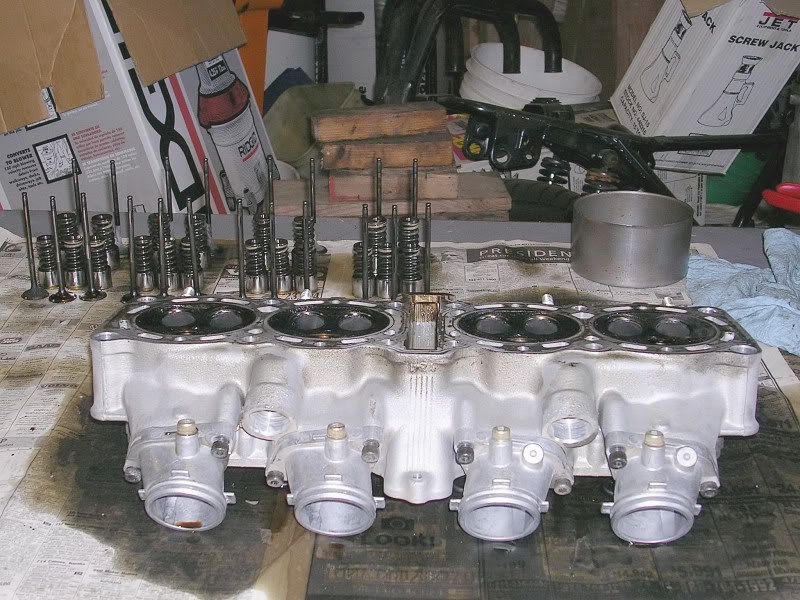
And finally - Tim wanted the valve seals replaced as long as it was down this far. Not that I disagree, but man is it a lot more work. A bit of an education for me on how intricate these twenty valve engines really are - So here is Twenty little valves all in a row...................
That's all the real progress for now, A bit more cleaning and re-assembly - and then all stop waiting for the new gears.
Cylinders were honed up nicely, and lot's of general cleaning work has been done. Big thanks to my pal Brad at X-act machine for letting me use a bit of his shop to get this done.
The gears provided a bit of a surprise - There was quite a bit of rounding on the second gear engagement dogs, and I'm waiting for a replacement set to find it's way here from Japan as I write this. I could not in good conscience build an engine with parts that I suspect wouldn't last too long, so (sigh) it's a bit of a hold up.
And finally - Tim wanted the valve seals replaced as long as it was down this far. Not that I disagree, but man is it a lot more work. A bit of an education for me on how intricate these twenty valve engines really are - So here is Twenty little valves all in a row...................
That's all the real progress for now, A bit more cleaning and re-assembly - and then all stop waiting for the new gears.
Last edited by ExupElvis on Mon Mar 27, 2006 7:39 am, edited 1 time in total.


The cases went into a jet-wash cabinet, kind of an industrial dish washer.
Hot chemical wash of some kind. And yes they can't be beat. Took a half hour to get that done.
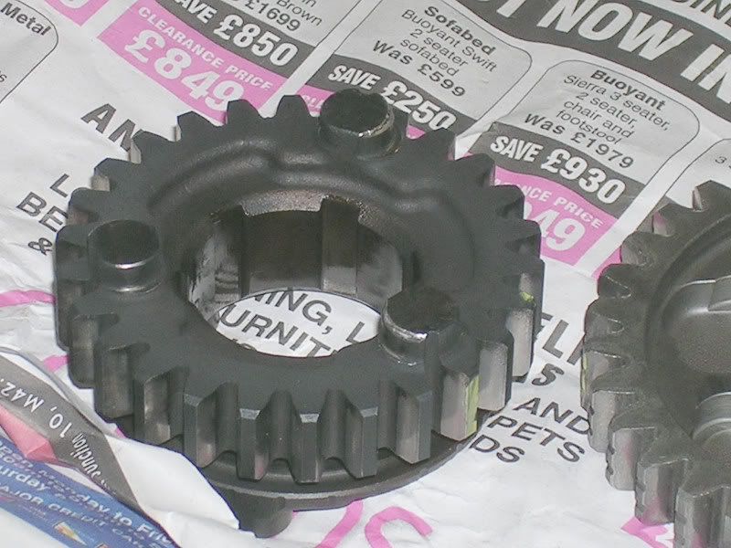
The trans felt really borderline when holding second gear engaged, and pulling the gears apart in the tourque direction, Simonsi.
The un-worn dogs won't pull out of engagement, but the worn second gear set did.
They will do the same thing when installed, only worse once oil is in there.
Since I didn't see that trans run, I have to err on the side of caution.
New set on the way though.
Hot chemical wash of some kind. And yes they can't be beat. Took a half hour to get that done.
The trans felt really borderline when holding second gear engaged, and pulling the gears apart in the tourque direction, Simonsi.
The un-worn dogs won't pull out of engagement, but the worn second gear set did.
They will do the same thing when installed, only worse once oil is in there.
Since I didn't see that trans run, I have to err on the side of caution.
New set on the way though.
-
FZRDude

- Co-Admin
- Posts: 4810
- Joined: Tue Jan 13, 2004 3:20 am
- Location: North-Left Coast, USA
- Contact:
More or less the principal of it now. I have the motor torn down, I've spent the money to get a 6-speed, so I might as well. And the frame isn't quite ready to have the motor put back in. So the timing of it happens to work out for me.Simonsi wrote:Sorry to hear that.
You could just buy gears for your old 5-speed gearbox. It would be cheaper
Stay tuned...
There are some who call me........Tim?
In Memory Of John "Silver" Douglas (Dec. 08, 2008) R.I.P. My Friend.


In Memory Of John "Silver" Douglas (Dec. 08, 2008) R.I.P. My Friend.
Valve Seals. Yup, That's right, Valve Seals........
I suppose I could have just pried off the old seals, crossed my fingers, and slipped the new ones on.
But this is a 30,000 mile engine. It had acquired some carbon and fuel deposits during those miles, and I felt it best to clean up the whole darn thing.
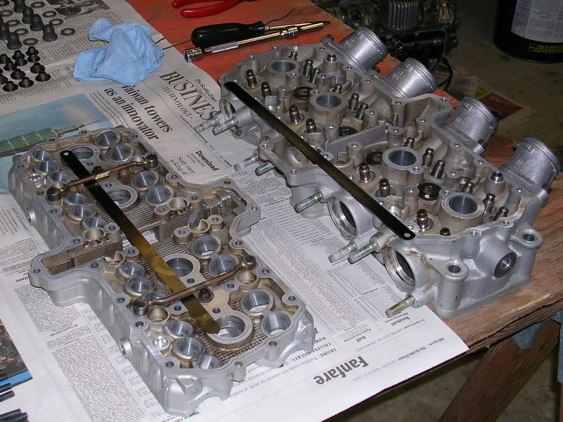
On inspection after cleaning up the valves and seats, it appeared that a lapping in would also be in order.................so here it is..........
I used a piece of steel dowl in a drill motor, and connected it to the valve stem with a piece of vaccum tubing to spin the valve. Some light cut compound got the job done, and it really did need doing. Some seats took two tries to clean up.
It was interesting to note that the seat and valve face materials differed a bit between intake and exhaust. Intakes cut the valve face more, exhaust was opposite. It was entertaining adjusting to which of the faces was cleaning and which needed a few more turns
So here's a few pics -
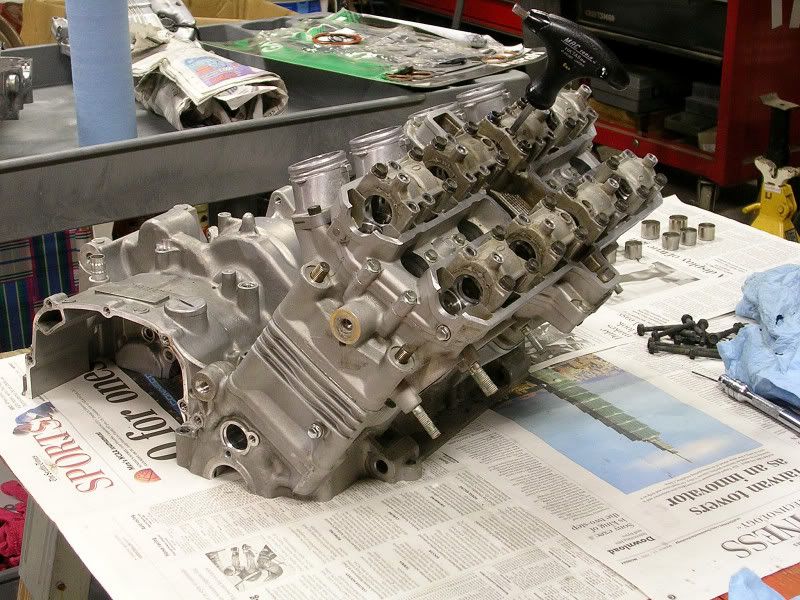
And here's a shot of most of the 285 parts I estimate this cylinder head contains when fully assembled - (That's without the valve cover).
I would like to get some shots of assembly/build/fitting when doing re-assembly, but it might be hard to do with oily fingers and all.
I'll try to do that though if there's any special requests, or if ya'll have seen enough - speak up and I'll honor that request too..............
But this is a 30,000 mile engine. It had acquired some carbon and fuel deposits during those miles, and I felt it best to clean up the whole darn thing.
On inspection after cleaning up the valves and seats, it appeared that a lapping in would also be in order.................so here it is..........
I used a piece of steel dowl in a drill motor, and connected it to the valve stem with a piece of vaccum tubing to spin the valve. Some light cut compound got the job done, and it really did need doing. Some seats took two tries to clean up.
It was interesting to note that the seat and valve face materials differed a bit between intake and exhaust. Intakes cut the valve face more, exhaust was opposite. It was entertaining adjusting to which of the faces was cleaning and which needed a few more turns
So here's a few pics -
And here's a shot of most of the 285 parts I estimate this cylinder head contains when fully assembled - (That's without the valve cover).
I would like to get some shots of assembly/build/fitting when doing re-assembly, but it might be hard to do with oily fingers and all.
I'll try to do that though if there's any special requests, or if ya'll have seen enough - speak up and I'll honor that request too..............
Last edited by ExupElvis on Wed Mar 29, 2006 2:51 am, edited 1 time in total.
-
barneyfzr600
- Help!!! I need a LIFE!!!
- Posts: 624
- Joined: Wed May 19, 2004 2:41 am
- Location: Cali. Bay Area
- Contact:
barneyfzr600 wrote:Wish my rebuild had been so nicely laid out! I had zip-lock bags everywhere! Not to mention oil..............
{P.S. - I know I been a slug on shipping for Ohhh.......5 months or so, but do you still want the '89 oil pan? It needs a new home......}
-
barneyfzr600
- Help!!! I need a LIFE!!!
- Posts: 624
- Joined: Wed May 19, 2004 2:41 am
- Location: Cali. Bay Area
- Contact:
Sometimes a picture isn't worth a thousand a words Hooli - I think this is one of those times.
I just couldn't get fully set up with the drill and the valve in the 10 second shutter delay my camera has.
So - valve lapping as opposed to valve grinding -
Grinding a valve and seat is renewing both surfaces with specialized tooling.
I won't take up space to go into all of it, but a re-surface (should) return both valve seat and face to new conditions. If the valve and /or seat are very badly worn, it is the only way to repair them.
Lapping will restore the seat/valve face seal without re-grinding, but it's really only usefull for mild wear and pitting.
Lapping simply means to put some abrasive compound between the valve seat and face, and spin the valve around a bit with mild pressure to hold the valve against the seat while it's spinning.
The valve seat is part of the head casting at the mouth of the port, the valve face is the angled contact face of the valve head itself. (just in case ya'll didn't know, don't shoot me for saying that!)
This is done with the springs off of course, and the head completley stripped in most cases, the lapping compound must be completely cleaned off after lapping, it isn't meant to be used for anything more than just the cutting process.
What the lapping compound does though is a mild version of what grinding does. It takes off and smooths irregularities such as high spots and pits that form on the valve sealing surfaces over time, which degrade the valve's sealing abilities.
The result is a restored valve seal surface with less material loss and valve recession than grinding.
In some ways lapping is a better process than grinding, and in others it's not.
It takes away slighty from the original three angles (or more) that the seat originally had when new, and can result in some flow loss. Lapping also increases the seat/valve contact (total) area a bit, and that has an effect on heat transfer from the valve head. To much isn't good, the valve will run cooler than it should and will be prone to carbon deposits. Lapping will never result in less contact area.
Grinding gives the machinist complete controll over the shape of the finished seat, but it also results in the the valve head ending up further down in the combustion chamber afterwords. No big deal in a big V-8 pushrod motor. It can be a little more to contend with when the cam is overhead and the valve stem only has so far to go before you lose adjusting clearance.
It's a compromise either way.
A light lapping to restore valve seating is generally a good thing if they clean up right away, and these did that pretty well.
Is that any help as far as explainations go?
I thought this was all some pretty neat stuff back when I was learning it in tech school, but anymore I have to look at engine parts a bit less like they're solid and finite, and a bit more like they are consumable parts of the power producing process.
Hope that wasn't too much.................
Last edited by ExupElvis on Tue Apr 18, 2006 1:01 am, edited 1 time in total.
elvis, that was perfect. all things to think about for my upcoming build. my father and uncle were both big pushrod motorheads back in their youth and have a bit of building experience between the two of them, so i got to learn quite a bit just being around. there are things like this however, that i need a bit of clarification on.
let me ask you this then, how does a "valve job" work. i read about 3 angle, 5 angle, multi angle valve jobs, do these also take material off the head and force the valve to "recede" farther from the combustion chamber or are new seats cut to restore the factory specs?
and finally, why the hell aren't the engine builders like jim and yourself on my side of the continent?
Jason, aka: Hooligan
1994 YZF750-R
1996 YZF750-R
2003 Bonneville T100
1994 YZF750-R
1996 YZF750-R
2003 Bonneville T100
It's a gravity thing Jason, I barely understand it myself...........and finally, why the hell aren't the engine builders like jim and yourself on my side of the continent?
(There are some pro shops there BTW, they're just really spendy).
I'll see if I can find some engine machining tutorial stuff and send it your way, there's a lot out there, but it's really a bit much to put in this thread.
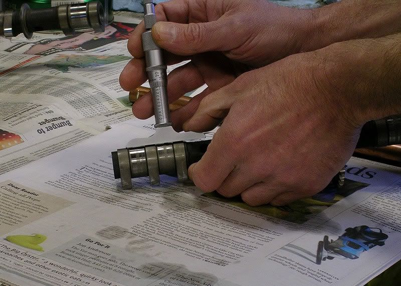
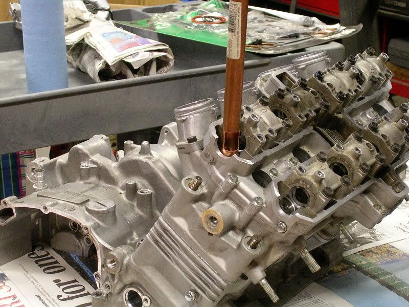
Ok, Up-date - the first two shots are of the simulation shim-stock, and loading a valve for stem height measurement. (The shim stock is needed because of the steel shim gasket which goes between the head and cam carrier which I won't install untill final assembly).
The rag holds the the valve against the seat, and needs to, as there are no springs in at this point.
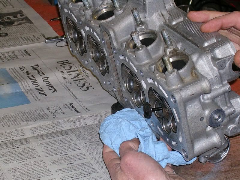
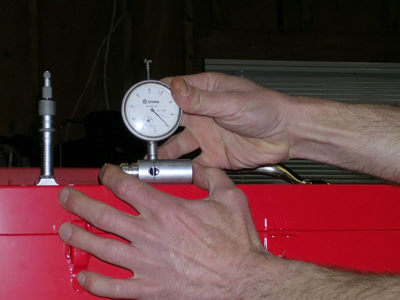
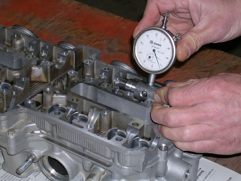
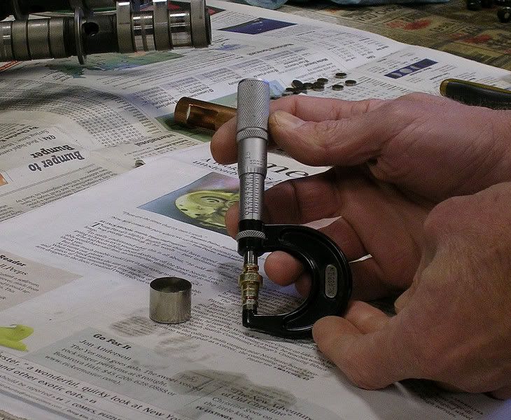
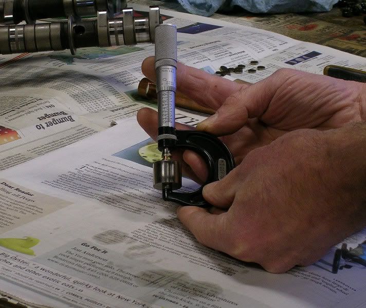
Next three pics are of the valve stem in position for measurement, and the the guage I used for height checking. The dial guage is nothing special. Comming up with the holding fixture is what kept me scratching my head for half a day. It turns out the oil pressure relief valve body is just the right size, and the spill ports work really well to pass the gauge tip through once the guts are removed.
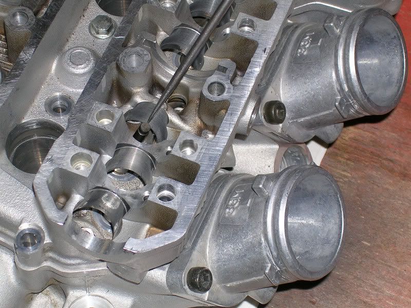
These pics show items to take into account that are between the cam MAIN journal diameter, and the valve stem tip - #1 is cam lobe base circle below the cam main
(if you look closely at the pics above, you can see I have to measure from the cam main bearing for an index point)
#'s 2&3 are measuring cam follower bucket thickness.
Add these two figures up, subtract them from the guage reading distance, add the shim thickness, and WA-LA! ..........A reasonable guess on valve clearance can be determined........
The next two are of the head assembled, with the second showing my top secret spring assembly tool (Hey, it worked).......
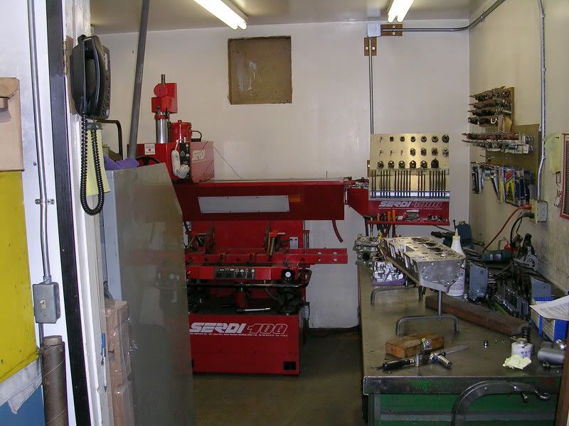
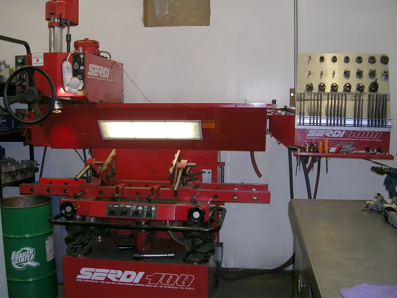
These pics are from the machine shop, first three here are of the Serdi seat and guide machine, which un-fortunately doesn't have the right size guide pilots for these teeny 4.5 mm stems. * I understand the pilots are available, but like anything else in specialty tooling - at a cost.
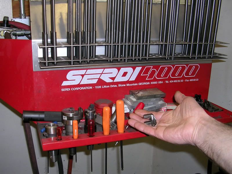
The last shot is for you Jason, those weird looking pieces are holders for the seat cutting tool bits.
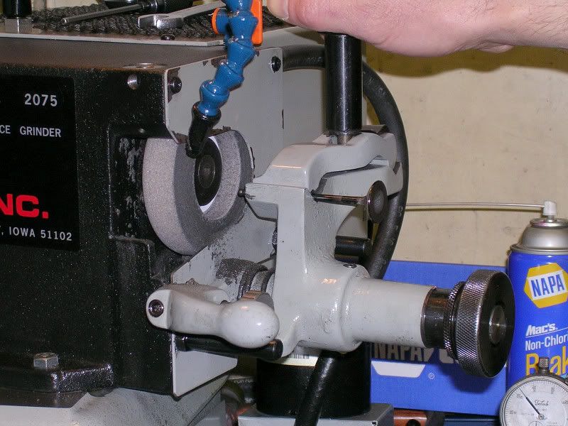
The next two are of a typical valve grinding machine, This is what I used to "tip" or shorten the valve stems. It didn't take much, but .003" to .006" per valve should allow re-use of all the original shims, and keep final assembly pretty straightforward. (There is PLENTY of room to make this adjustment on the Fizzer 1 liters, and it should be done if a head is getting into real thin shims to maintain clearance).
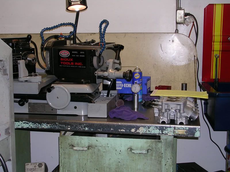
This pic is of a typical old school valve seat bench for stone wheel grinding, these are still commonly used for automotive work - reasonably fast, really dirty, and the tooling works Ok with broom-handle sized valve stems.

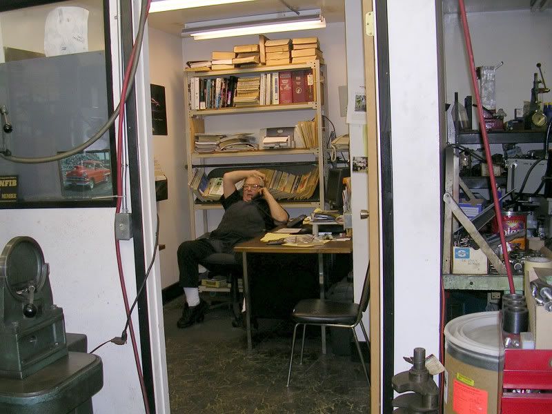
Here is Brad steeling himself for another one my irritating visits......
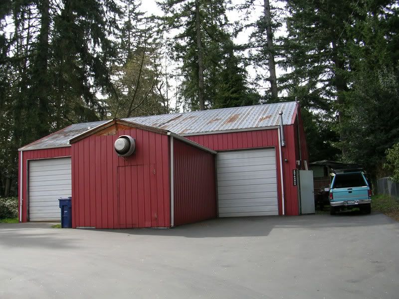
And finally, the top secret and very un-assuming skunkworks that is X-act machine
I still have to fit all the shims and double check clearances, but hopefully this is a somewhat usefull explaination of setting up a cylinder head.
So untill I get some gears, that's kind of going to have to do for a while......
The rag holds the the valve against the seat, and needs to, as there are no springs in at this point.
Next three pics are of the valve stem in position for measurement, and the the guage I used for height checking. The dial guage is nothing special. Comming up with the holding fixture is what kept me scratching my head for half a day. It turns out the oil pressure relief valve body is just the right size, and the spill ports work really well to pass the gauge tip through once the guts are removed.
These pics show items to take into account that are between the cam MAIN journal diameter, and the valve stem tip - #1 is cam lobe base circle below the cam main
(if you look closely at the pics above, you can see I have to measure from the cam main bearing for an index point)
#'s 2&3 are measuring cam follower bucket thickness.
Add these two figures up, subtract them from the guage reading distance, add the shim thickness, and WA-LA! ..........A reasonable guess on valve clearance can be determined........
The next two are of the head assembled, with the second showing my top secret spring assembly tool (Hey, it worked).......
These pics are from the machine shop, first three here are of the Serdi seat and guide machine, which un-fortunately doesn't have the right size guide pilots for these teeny 4.5 mm stems. * I understand the pilots are available, but like anything else in specialty tooling - at a cost.
The last shot is for you Jason, those weird looking pieces are holders for the seat cutting tool bits.
The next two are of a typical valve grinding machine, This is what I used to "tip" or shorten the valve stems. It didn't take much, but .003" to .006" per valve should allow re-use of all the original shims, and keep final assembly pretty straightforward. (There is PLENTY of room to make this adjustment on the Fizzer 1 liters, and it should be done if a head is getting into real thin shims to maintain clearance).
This pic is of a typical old school valve seat bench for stone wheel grinding, these are still commonly used for automotive work - reasonably fast, really dirty, and the tooling works Ok with broom-handle sized valve stems.
Here is Brad steeling himself for another one my irritating visits......
And finally, the top secret and very un-assuming skunkworks that is X-act machine
I still have to fit all the shims and double check clearances, but hopefully this is a somewhat usefull explaination of setting up a cylinder head.
So untill I get some gears, that's kind of going to have to do for a while......